Choosing a high-performance, feature-rich MCU for Mahymah: STM32H753
By Milind
/
July 9, 2025
This is the second part of our series on the development of the Aerowint Mahymah flight controller—a powerful, feature-packed solution designed for next-generation multi-domain UAVs. Designing a flight controller like Mahymah for advanced, feature-rich UAVs demands more than just raw performance— it requires a precise balance of computational efficiency, rich feature integration, low power consumption and uncompromising reliability. In this blog, we will walk through the details of this process and explain the options we considered and the approach we followed.
The previous part of this series introduced the project, outlined its ambitious capabilities, features and roadmap. This part picks up from where we left off, delving into the critical first component, i.e. the MCU.
This sophisticated flight controller is being entirely designed and manufactured in India, embodying our philosophy of "Making in India, Making for the World."
Architecture & vendor considerations
This section goes through the first part of the selection process — choosing a suitable architecture/family for the MCU, and a vendor capable of delivering it.
Just like any engineering process, the process starts with listing our functional & non-functional requirements, constraints and assigning priorities to them. In our case, this was relatively quick.
Requirements
- Performance -
- Built-in FPU for fast and precise floating-point calculations required for flight control.
- Built-in cryptographic acceleration for secure boot and encrypted communication (Hashing, RNG etc.)
- ≥ 300 MHz clock speed to allow core processing and machine learning execution.
- Connectivity -
- Atleast ×4 SPI ports, to connect Triple IMUs and Barometer.(a fifth SPI port can be used to add external expandability).
- Atleast ×2 I2C ports, to connect a Barometer and Magnetometer (a third I2C port can be used to add external expandability).
- Atleast ×4 UART ports, to connect IBUS, Telemetry, GPS, and a spare port for external payloads.
- Atleast ×2 FD-CAN port, to connect camera circuitry or redundant GPS or other external payloads.
- ×1 SDIO port for connecting a Micro SD Card to use as a blackbox/logging.
- 10/100/1000 Mbps Ethernet for high-speed wired networking and real-time data exchange, compliant with IEEE802.3/802.3u (Fast Ethernet) and ISO 802-3/IEEE 802.3 (10BASE-T).
- Built-in USB peripheral mode hardware, for firmware uploads, virtual COM ports, etc.
- DCMI camera interface for connecting a parallel camera module.
- Footprint -
- LQFP or QFN package for its ease of PCB routing, and compatibility with manufacturers.
- Miscellaneous -
- ≥ 4 timers for adequate PWM channels and high-precision timing.
- 5V tolerant I/O, atleast for UART and CAN.
- Reasonably low power consumption.
In particular, these requirements are derived from the capabilities of the final flight controller, which were listed in the first part of this series.
Constraints
We had a single constraint — the chip must not have a BGA package. This would have led to more complex routing with tighter constraints and riskier assembly.
The compactness offered by BGA packages were not worth the trade-off in the first version of the controller, and we decided to use this in the next versions of the controller.
Future enhancements: NPU, GPU, and AI integration
Looking ahead, future iterations of the Mahymah flight controller will incorporate advanced AI capabilities by integrating dedicated hardware such as NPUs (Neural Processing Units), GPUs (Graphics Processing Units) and other accelerators for AI and computer vision tasks. To support this evolution, an MCU having the necessary NPU/GPU and other AI hardware accelerators capable of handling such workloads will be selected, ensuring the platform remains optimized for high-performance and real-time AI processing.
This evolution will enable real-time obstacle avoidance, object tracking and other vision processing, allowing low-latency decision-making on the edge, enhancing safety, reliability and reducing the Pilot's cognitive load.
AI capabilities are crucial for operations in risky/congested/chaotic environments such as indoors, underground, tunnels, pipelines and GNSS-denied spaces. With onboard processing, the Mahymah can significantly reduce cognitive load on the Pilot by allowing low-latency obstacle-avoidance, object recognition & tracking, visual-inertial odometry.
Software development kit & framework considerations
Apart from the above well-defined requirements, having a good software development kit was essential for quick evaluation in the short-term, and fast development in the long-term. We did not wish to deal with half-baked tools, incomplete documentation, lack of support, etc.
The second floor of a building can only be as strong as the first.
Just as we intend to provide a high-quality and reliable product for our customers to stand by, we need a high-quality and reliable foundation to build from.
From the above, it was clear that either ARM Cortex M or RISC-V would be an ideal choice. x86 would be too bulky, while other architectures were too cryptic (from our point of view and research).
Both the above architectures were based on RISC principles (Reduced Instruction Set Computing), which is opposed to CISC (Complex Instruction Set Computing) principles commonly found in high-performance consumer devices (such as laptops, phones, tablets etc.). At our level, both ARM Cortex M and RISC-V provided similar capabilities, and it was difficult to choose between the two.
Finally we settled on ARM Cortex M due to its superior stability, support, maturity of tools etc. RISC-V was too volatile to bet on, and the vendors such as Espressif who did have some stability and reputation were out of the equation. However, we will still consider RISC-V for future designs.
The next step was to choose a vendor. This was a fairly quick step as we had a clear idea of what we wanted, and most vendors make it easy to filter through their MCUs based on one's requirements. We settled on STMicroelectronics (coloquially known as ST and STM32) due to their support, availability and our familiarity with their SDK.
For those who are confused about why we didn't just buy an ARM Cortex M controller, here is why:
ARM is not a company that sells physical processors/controllers. Instead, they create IPs (Intellectual Property), i.e. processor designs, which are licensed by actual vendors who use these in their products. A single "ARM" processor created by a vendor such as ST or Renesas is a physical chip that can include one or more processor cores (as defined by ARM), along with storage, memory, connectivity, peripherals etc. (as defined by the vendor).
NXP, Nordic and Renesas were all considered as vendors but discarded for the following reasons -
- Renesas was not friendly for small-medium developers/companies, and had a disappointing SDK. They do not support all the features of the processor as given in the datasheet, or have proper support for Clang or GCC, the latter of which we intend to use.
The only reason for considering it in the first place was its usage in the Arduino UNO R4, but we quickly discovered that it was not a good fit for us. - Nordic was a strong contender, but we simply did not want to entangle with the Zephyr Project, which was part of their default SDK. Our past experience with Zephyr for projects was poor, and the overhead of Zephyr binaries did not do anything to help their case.
Perhaps in the future, we will consider Zephyr but it was not something we wanted to deal with now. - NXP was the most promising contender to ST. They had no strong demerits, but we had greater familiarity with ST, and felt like the STM32Cube framework was a tad easier to work with. We will consider using NXP in our future designs to prevent dependence on a single vendor.
Yet another reason to go with ST was due to Ardupilot Support. This becomes an even more important point in the next section when we choose an MCU. Ardupilot has almost exclusive support for STM32 MCUs, and our experience from their forums , they were generally averse to other vendors. We didn't intend for Ardupilot support to be a hard constraint, but it was still a factor to consider and a good-to-have capability.
Core & microcontroller selection
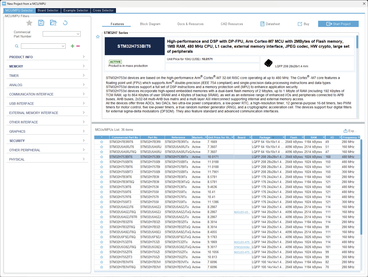
Having chosen STMicroelectronics as our vendor, the next was to choose a suitable MCU for our needs. Fortunately, ST provides the STM32CubeMX software for this as part of their STM32 Cube framework.
STM32Cube is a comprehensive ecosystem of software tools and embedded software libraries from STMicroelectronics designed to simplify and accelerate development for STM32 microcontrollers and microprocessors, offering a complete development cycle from configuration to debugging.
STM32CubeMX is a graphical tool that comes as a part of STM32Cube, which allows us to search for MCUs, and generate and configure projects for them. This saves a lot of time compared to manual configuration, which involves perusing through the datasheet and setting each register manually.
This was a simple process — using the filters to communicate our requirements to the tool and selecting the best option from the given results -
Apart from the requirements listed in the previous section, we added the following filters -
- The chip must be active, i.e. not discontinued/NRND (not recommended for new designs).
- ≥ 1M Flash, to comfortably support large-scale modular firmware, and potential compatibility with open-source autopilot stacks like ArduPilot[1] and PX4.[2] (if we ever decide to port it).
- ≥ 128K RAM, as this was the lowest amount that was atleast 10% of the storage, which was required to make the Flash productive.
- High-speed interfaces such as Ethernet, USB OTG, SDMMC, SPI, I2C and multiple USARTs to accommodate a wide variety of peripherals without requiring external controllers.
- A trusted security and memory protection unit (MPU) to support secure boot, firmware updates, and isolation of critical code.
After filtering and evaluating several options, STM32H753BIT6 emerged as the clear choice. It combines a 480 MHz ARM Cortex-M7 core, 2MB Flash, 1MB RAM, rich peripheral set and hardware crypto, while still maintaining the flexibility and power efficiency required for a high-performance UAV system.
We had initially considered other MCUs like the STM32F7 and STM32G4 series, but they either lacked the required memory/performance headroom or didn't offer enough peripheral flexibility for our long-term roadmap. The STM32H7 series, and in particular the H753, provided the perfect balance of computational power, expandability, and reliability for the next generation of intelligent flight controllers.
Later in the development process, we transitioned to using the STM32H753VIT6 variant in the actual Mahymah flight controller. Functionally identical to the STM32H753BIT6, the VIT6 offers the same performance and peripheral set but comes in a more compact 14 × 14 mm LQFP100 package, making it better suited for our size-constrained PCB layout while maintaining full compatibility with our design.
The STM32H753 possesses the following features in terms of performance -
- ARM Cortex M7 core clocked at upto 480 MHz
- 6-stage superscalar pipeline with dual-issue capability
- Hardware 32-bit double-precision FPU (Floating Point Unit)
- Dedicated Cryptographic Unit (for hashing, AES, TDES, etc.)
- True Random number generator
- Achieves a performance of 1027 DMIPS, with an efficiency of 2.14 DMIPS per MHz
- Dedicated CRC (Cyclic Redundancy Checker) Unit
- Dual mode Quad-SPI memory interface running up to 133 MHz
- NVIC, DMA and other peripherals
- Enhanced Harvard architecture with tightly coupled memory (TCM)
And the following in terms of IO -
- ×2 FDCAN ports (×1 used)
- ×4 I2C ports (×3 used)
- ×6 SPI ports (×5 used)
- ×5 UART ports (×5 used)
- ×2 USB ports (×1 used)
- ×2 SDMMC port (×1 used)
- ×1 Ethernet MAC interface (×1 used)
- ×1 FSMC (not used yet)
- ×4 Serial Audio Interface (not used yet)
- ×1 HDMI-CEC (not used yet)
- ×1 DCMI Interface (not used yet)
- ×38 ADC channels (×8 used)
- ×2 DAC channels (×1 used)
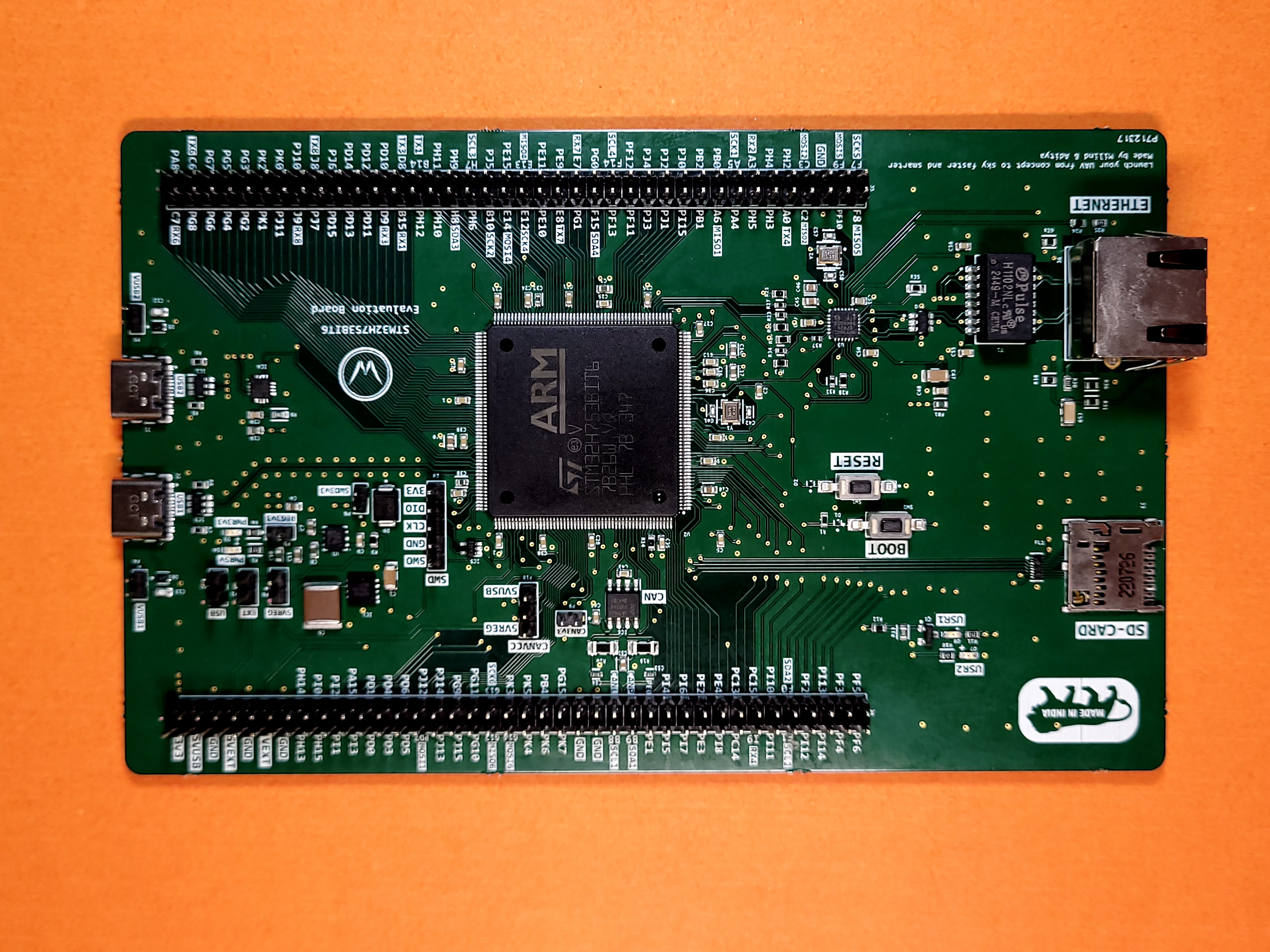
Designing an evaluation board
This section walks through the process of designing an evaluation board for the STM32H753BIT6, which is the next step after selecting the MCU. It would have been slightly faster (and affordable) to buy a pre-existing evaluation board, but since one was not easily available (and we would have to design our own board anyway), we decided to design it ourselves and get it manufactured.
The final board, (major components labelled), looks as follows -
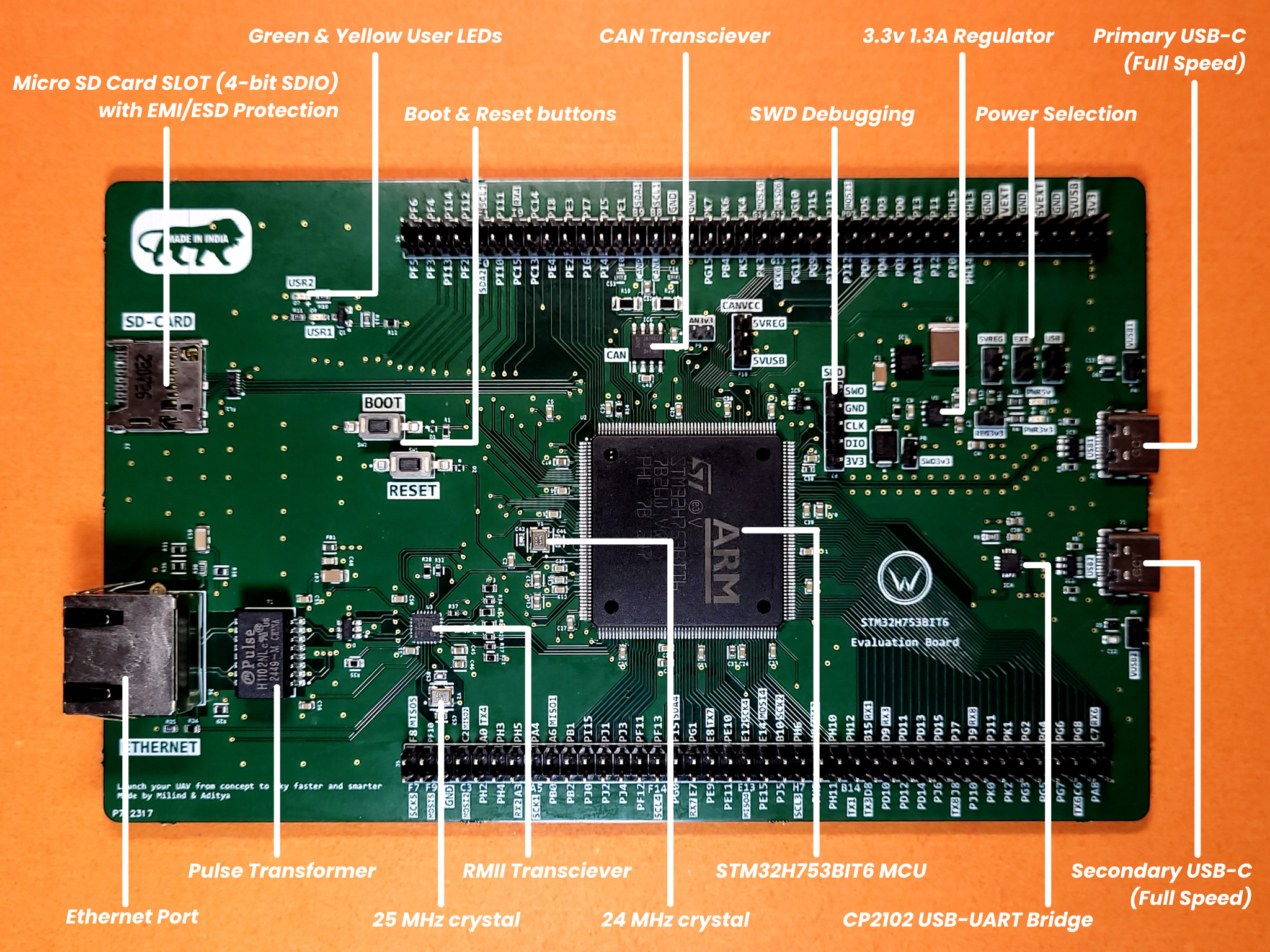
The evaluation board was designed to be reusable beyond the scope of this project alone, but still not be too generalized. Keeping this in mind, let us look at the key features of the board, and how they enable us to use the features of the MCU -
- CP2102 USB-UART Bridge from Silicon Labs ensures reliable and independent serial communication, ideal for real-time debugging and telemetry
- ×2 USB-C ports with USB 2.0 full speed and surge protection.
- SWD debugging port with ESD protection and surge protection.
- Dedicated Boot and Reset buttons with ESD and surge protection.
- Built-in micro SD Card slot with EMI filter and ESD protection.
- Dedicated 24 MHz crystal (for High-Speed Oscillator).
- TJA1462 CAN transceiver which supports Classical CAN and CAN FD
- Ethernet support with RMII transceiver, pulse transformer, and Bob Smith termination for EMI reduction and reliable high-speed communication
- 25 MHz crystal dedicated for Ethernet
- Power selection jumpers for USB 1, USB 2, and external (regulated & unregulated) power
Starting with the USB-C, this was chosen to keep the board future-proof. As of writing this blog (Q3 2025), Micro-USB, USB-A, and other USB ports are on their way out. USB-C aims to combine the features and benefits of all the standards whilst also providing superior reliability, power delivery and most importantly - reversibility.
The CP2102 chip was added to act as a simple and reliable method of communication with the flight controller. The MCU already has a USB port which could function as a virtual com port (VCP), but the firmware and operation was fairly complex with a lot of moving parts. This made it a bad fit for a reliable communication stream that is required for debugging, critical messaging etc. It could still be used to flash firmware or perform other tasks, but all forms of critical communication was better assigned to a hardware UART port, where the number of moving parts (and therefore risk of failure) was lower.
The Ethernet interface was designed to support high-speed, low-latency communication between the flight controller and external systems such as ground control stations or companion computers. RMII was chosen over traditional MII to reduce the number of required pins, freeing up valuable IO on the MCU for other subsystems. A pulse transformer was added to provide galvanic isolation and reduce the risk of electrical interference or ground loops. Additionally, Bob Smith termination was included to minimize common-mode noise and improve EMI performance — both critical considerations in electrically noisy environments like UAVs.
The onboard CAN interface was added to enable reliable, high-speed communication between subsystems or other external payloads. The TJA1462 CAN transceiver was chosen for its robust performance, low power consumption, and integrated protection features. It supports both Classical CAN and CAN FD, offering greater data throughput and flexibility for modern UAV communication needs.
All user-accessible components, including the USB-C ports, Boot & Reset buttons, SWD header, microSD slot, and Ethernet connector, have been protected with ESD and surge protection. This ensures that accidental static discharge, power surges, or repeated handling during development and testing do not compromise the reliability of the board or damage the MCU and supporting components. These protections are essential for building a robust and field-ready flight controller platform.
The remaining features are self-explanatory when considering the capabilities of the MCU and final flight controller, making them necessary for thorough evaluation of the MCU.
Conclusion
The STM32H753 has emerged as the ideal choice for our multi-domain flight controller, offering an excellent balance of high performance, rich peripheral set, memory headroom, and future scalability. With this selection finalized, the next step involved designing evaluation hardware around the MCU, integrating critical peripherals like sensors and communication interfaces, and beginning firmware development tailored for high-performance UAV applications.
The next step is to procure the various sensor breakouts and write the drivers to run them, along with testing everything using the H7 evaluation board shown in this post.
Through this blog, we hope to build transparency with our community by sharing our development and engineering process. If you have any thoughts or suggestions, you can share them with us at aerowint.com/contact, or write to our founders directly at milind@aerowint.com or aditya@aerowint.com.