Choosing a low-noise, reliable IMU for Anymah: ICM45686
By Aditya
/
April 8, 2025
This is the third part of our series on the development of the Aerowint Anymah flight controller, an ultra-light, compact and high-performance solution designed specifically for the next-generation nano UAVs. Designing a flight controller for compact, agile UAVs is a balancing act — finding the right compromise between small-size, high-performance and reliability is a challenge. In this blog, we will walk through the details of this process and explain the options we considered, and the approach we followed.
The previous part of this series talked about choosing an MCU which struck an appropriate compromize between size, performance, power-consumption and had availability. This part continues from here and goes into the next most important component, i.e. the IMU.
This sophisticated flight controller is being entirely designed and manufactured in India, embodying our philosophy of "Making in India, Making for the World."
Requirements and constraints while choosing an IMU
This section goes through the first part of the selection process - listing the requirements and constraints that must be considered while selecting the IMU and prioritizing them. This was a relatively quick process.
Requirements
- Low-noise on both the accelerometer & gyroscope, especially to allow stability in high-speed aerial maneuvers that nano drones generally perform.
- High-sampling rates, atleast 5 KHz (twice our intended loop frequency) to allow faster response to disturbances.
- Good thermal stability to ensure reliability through different climates and seasons, especially in longer missions.
- Fast SPI interface, allowing fast data transfer from the IMU to MCU (as compared to UART or I2C). Using SPI also allows the use of DMA, which doesn't work as well with other protocols.
- Good documentation and support to facilitate platform-agnostic software driver design and implementation.
- Low power consumption, to allow greater flight time, especially in nano drones with smaller and lighter batteries.
- Optional onboard processing of data, to reduce the load on the MCU while performing filtering and sensor fusion, and also add some extra redundancy.
Constraints
- The sensor must have reasonable cost & availability.
The constraint listed above seems quite obvious, but presents an important point. We did not want to go with an exotic, cutting-edge sensor (such as photonics) which would be overkill for our purpose. We needed reasonable performance at reasonable pricing with strong availability, not a research platform, for a production-grade flight controller.
Based on the above, it was clear that most hobbyist sensors, such as the MPU6050/6000/9250 were not the best fit for us despite their ubiquity and low-cost. More modern sensors provided much better performance and power-consumption without being proportionally more expensive.
Vendors and options considered
Having listed the requirements, we finally narrowed down the search to 3 vendors - STMicroelectronics, Bosch & TDK. Each were popular silicon vendors with a strong supply-chain, support, documentation and portfolio of IMUs (and other sensors too).
Finally, we chose the ICM-45686P from TDK Invense, as we found it to have the lowest power-consumption and great performance. Here are all the options that we considered and why we rejected them -
- ASM330LHH (automotive series 6-axis IMU) from STMicroelectronics - This was the next strongest contender due to its low-cost and great documentation, and even had slightly lower accelerometer noise compared to the ICM-45686P. It lost nonetheless, due to having a higher gyroscope noise-density and power-consumption (almost twice the power-consumption of the ICM-45686P). In most other aspects, it was fairly similar to the ICM-45686P.
- BMI088 from Bosch - This was quickly rejected due to its awkward shape and interface, which made it hard to place on a nano-flight controller. Furthermore, its performance and power-consumption were better than hobbyist IMUs, but still considerably inferior to both ST and TDK's offering.
- ICM-42688P from TDK - This was quite similar to the ICM-45686P (as both were from the same vendor), but had greater noise and a higher power-consumption, due to being slightly older.
Recently, Bosch has released successors to the BMI088 which offer better performance and smaller sizes, no doubt to keep up with its competitors. However, we were not comfortable with using such new sensors, especially given that slightly established alternatives existed with equivalent features.
Yet another reason for choosing the ICM-45686 is the fact that it is used in Pixhawk controllers as well. We want to choose our sensors based on the datasheet and numbers, but it also helps that a popular flight controller platform already uses the same sensor.
Designing an evaluation board
This section walks through the process of creating an evaluation board for the ICM-45686P, which is the next step after selecting the sensor. It would have been better to buy a pre-existing evaluation board, but we couldn't find any (atleast, not from a reliable source) and therefore decided to make our own.
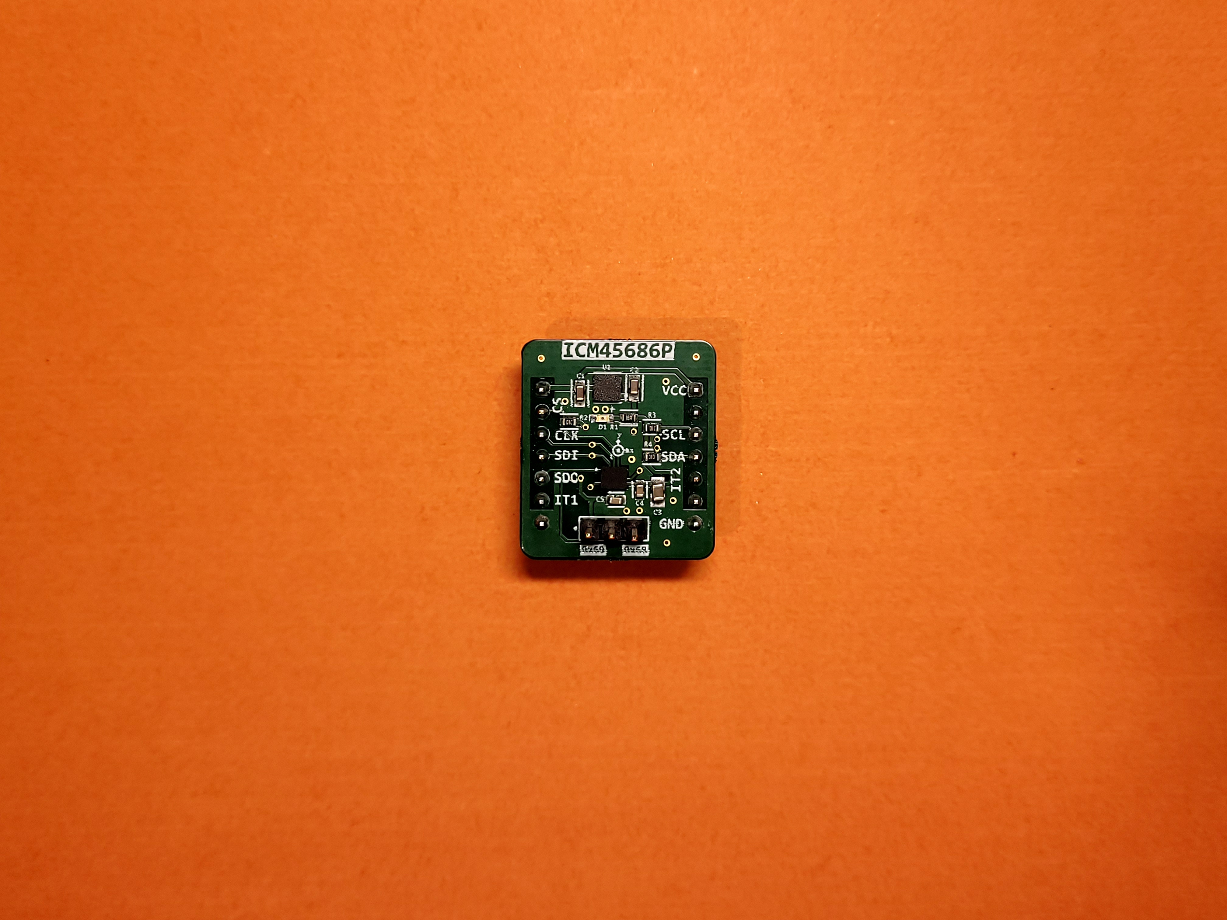
The final board (labelled) looks as shown -
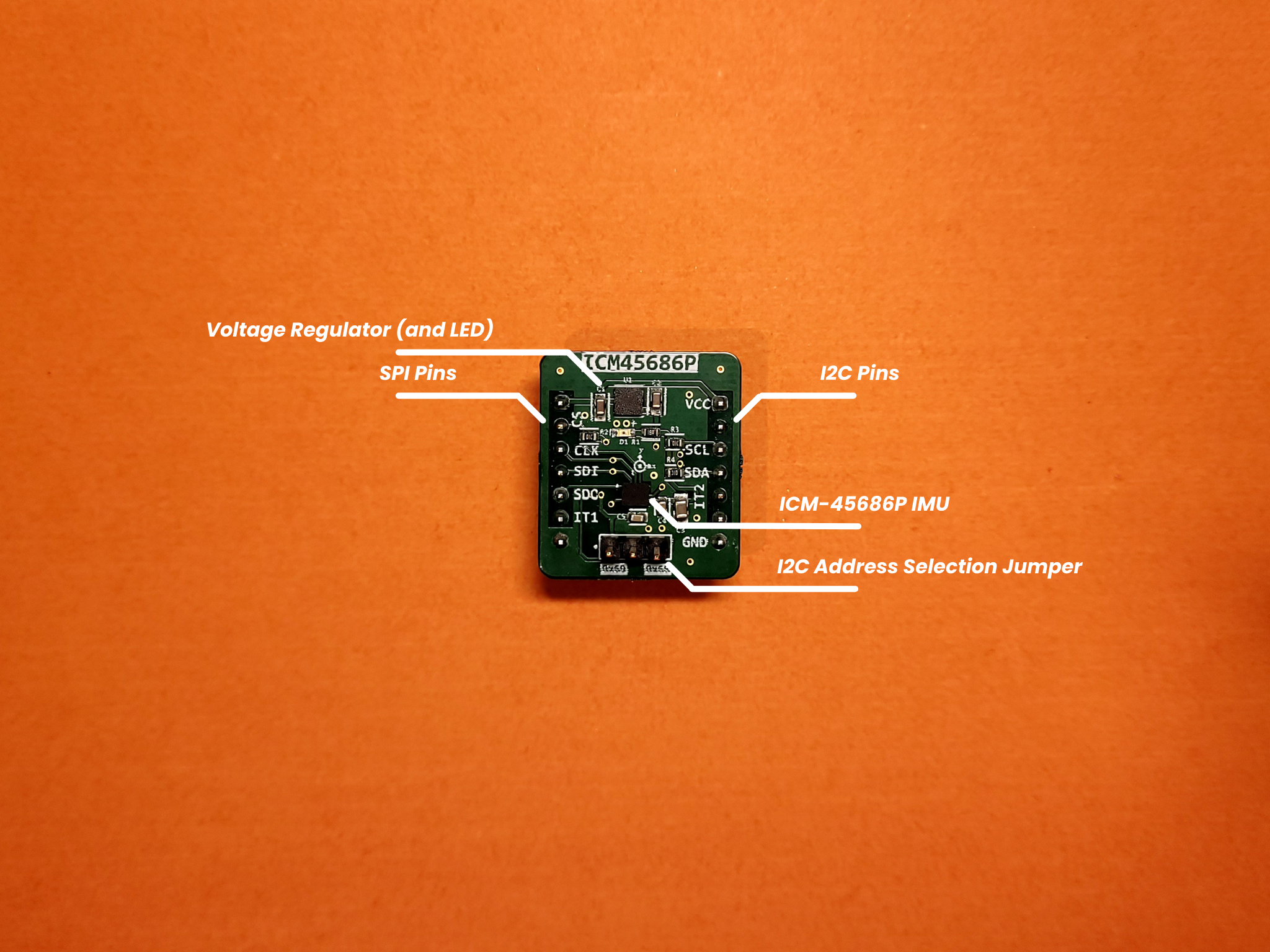
The evaluation board was designed to be simple, breadboard-friendly and re-usable beyond this project. It has the following features kept fairly simple and had the following features -
- Dedicated voltage regulator and power LED - We used the LD39200 voltage regulator from ST, which is an ultra-low drop linear regulator with reverse current protection. The LD39200 has anadjustable voltage output and can supply a generous 2A. Additionally, it has a voltage drop of merely 0.13v at maximum load. Most importantly, the regulator has a wide input range, from 1.25v to 6v. In our case, we wanted 3.3v, and could power the board from an external 5v or 3.3v source without worrying about the sensor burning.
- Separate headers for I2C, SPI and interrupts - The purpose of the breakout board is to break out the pins of the IC for convenient use. We decided to create separate rows for I2C and SPI on either side of the board, and make it breadboard friendly. This makes it much easier to evaluate the sensor than if the pins were shared and only on one side.
- I2C address selection headers - These allow us to use shunt connectors to conveniently select the I2C headers, without messy wiring or ad-hoc soldering.
- Pull-up resistor on Chip-Select and I2C Pins - This removes the need for external pull-up resistors, thus reducing evaluation time.
A potential improvement in the breakout would be the addition of the Adafruit Qwiic connector, which would make it compatible with a vast ecosystem of sensors.
Given that this sensor is an IMU, being able to mount it on a breadbord is quite helpful. This is because it can be mounted on a fixed platform with the other sensors, giving a stable and shared reference frame for all readings. If the pins were instead on a single side (requiring direct wiring to the MCU), all the sensors would be dangling from wires, making it impossible to test vibration resistance & sensor fusion algorithms.
Creating a platform-agnostic software driver
After designing the physical breakout board, we needed a robust software foundation to maximize the potential of the ICM-45686P. Our goal was to create a driver that wasn't just functional but adaptable across multiple platforms and projects. This approach aligns with our philosophy of building reusable components that provide long-term value.
Architecture for flexibility and performance
Our driver architecture provides a layered approach with clear separation of concerns -
The key to platform agnosticism lies in our Hardware Abstraction Layer (HAL). We designed an interface structure that defines the essential communication functions -
And functions of the following form -
The init, configuration and data functions implement the logic of executing a transaction with the IMU, by using the functions pointed to by the interface structure. This allows the consumer of the driver to implement the communication for their platform and communication protocol (SPI or I2C).
This structure allows us to inject platform-specific implementations while keeping the core driver logic consistent. Whether we're running on an STM32, ESP32, or any other microcontroller, the driver's behavior remains predictable.
Handling DMA in a cross-platform mannger
For high-speed sampling applications like flight control, Direct Memory Access (DMA) is crucial. Our driver provides both polling-based and DMA-based reading modes.
Specifically when using DMA, the driver provides a function to start the DMA process, and another function which to be called on the completion of the DMA transfer. This allows the DMA read functionality to be performed in a cross-platform manner.
Instrumentation
Beyond simply using the sensor, the driver also includes instrumentation to provide insights into usage and speed-up debugging in case of errors or unexpected behaviour -
- Performance metrics tracking - Our driver maintains statistics on communication speed and failure rate.
- Self-diagnosis - Our driver implemented self-test functionality which works with the built-in self-test functionality of the sensor to give exceptional reliability.
Evaluation process
After finishing the hardware and software development process, the next steps are to thoroughly use the sensor in dynamic environments (such as stationary, vibrating, oscillating etc.) and test various sensor fusion algorithms.
The first part of the evaluation process is to individually test the breakout board and software driver with the STM32F4 MCU breakout board (from the previous part), similar to unit testing in software development. Once proper functioning has been determined, the next step is to place the sensor in various environments (static, vibrating, oscillating etc.) and characterize its tolerance, power-consumption etc.
After testing the sensor individually, the next step is to combine data from multiple sensors (multiple IMUs as well as other kinds of sensors) to characterize sensor fusion algorithms, which will be covered in a separate blog.
Conclusion
The ICM-45686 has emerged as a suitable choice for our nano flight controller, offering great performance and efficiency whilst being low-cost and small. We will use two of these on our flight controller to add redundancy and improve resistance to drift and vibration.
The next step involves choosing and evaluating a barometer (air-pressure sensor), which will follow a similar process to the IMU.
Through this blog, we hope to build transparency with our community by sharing our development and engineering process. If you have any thoughts or suggestions, you can share them with us at aerowint.com/contact, or write to our founders directly at aditya@aerowint.com or milind@aerowint.com.