Choosing a stable, low-hysteresis Magnetometer: IST8310
By Milind
/
June 26, 2025
Accurate heading estimation is fundamental to reliable drone navigation, especially in autonomous systems and GPS-denied environments. At the heart of this lies the magnetometer, a sensor responsible for detecting the Earth's magnetic field to determine the yaw or compass direction. Selecting the right magnetometer involves balancing size, precision, thermal stability, and resilience to interference from surrounding electronics like motors and ESCs.
In this post, we explore our evaluation process and the technical reasoning that led us to choose the IST8310, a compact, low-noise, and thermally stable 3-axis digital magnetometer that fits the stringent requirements of modern UAV applications. This selection supports our ongoing effort to develop high-performance drone systems — designed and built in India, for deployment worldwide.
Requirements and constraints while choosing a Magnetometer
This section goes through the first part of the selection process - listing the requirements and constraints that must be considered while selecting the Magnetometer and prioritizing them. This was a relatively quick process.
Requirements
- Wide dynamic range to handle varying magnetic field strengths, ensuring accurate readings in both low-field environments (e.g., indoors) and high-field environments.
- Low hysteresis to ensure the sensor maintains heading accuracy and quickly recovers after exposure to strong or fluctuating magnetic fields, such as those generated by drone motors, ESCs, or power lines.
- Low noise and high resolution for precise heading, allowing the magnetometer to detect subtle changes in the magnetic field, which results in smoother yaw estimation and more accurate magnetic heading.
- Minimal temperature drift to ensure consistent output even in changing environmental conditions during flight.
- Good documentation and support to facilitate platform-agnostic software driver design and implementation.
Constraints
- The sensor must have reasonable cost & availability.
The constraint listed above seems quite obvious, but presents an important point. An exotic cutting-edge sensor would be overkill for our purpose, and we needed reasonable performance at reasonable pricing with strong availability, not a research platform, for a production-grade flight controller.
Vendors and options considered
Having listed the requirements, we finally narrowed down the search to 3 vendors - Honeywell, Bosch & iSentek. Each were popular silicon vendors with a strong supply-chain, support, documentation and portfolio of Magnetometers (and other sensors too).
Finally, we chose the IST8310 from iSentek, as we found it to have the best combination of Temperature Stability, Dynamic Range, Availability and Ease of Assembly. Here are all the options that we considered and why we rejected them -
- BMM350 from Bosch - This was the next strongest contender due to its low-cost, compact-size and superior performance. However, it comes in a WLCSP (Wafer Level Chip Scale Package), which we initially avoided as we were also in the process of testing our PCB manufacturer's capabilities and preferred using easier-to-assemble packages during early prototyping.
- HMC5883L from Honeywell - This was rejected due to its legacy status and lack of ongoing support. Its thermal performance was poor, and it demonstrated significant offset drift in varying temperatures — disqualifying it for modern, production-grade systems.
- BMM150 from Bosch - This was quickly rejected due to its limited dynamic magnetic field range which made it unsuitable for industry-grade UAVs. The BMM150 is also an obsolete product and is not supported by the Bosch community anymore.
Designing an evaluation board
This section walks through the process of creating an evaluation board for the IST8310, which is the next step after selecting the sensor. It would have been better to buy a pre-existing evaluation board, but we decided to make our own to verify the decoupling capacitors and the I2C interface routing ourselves.
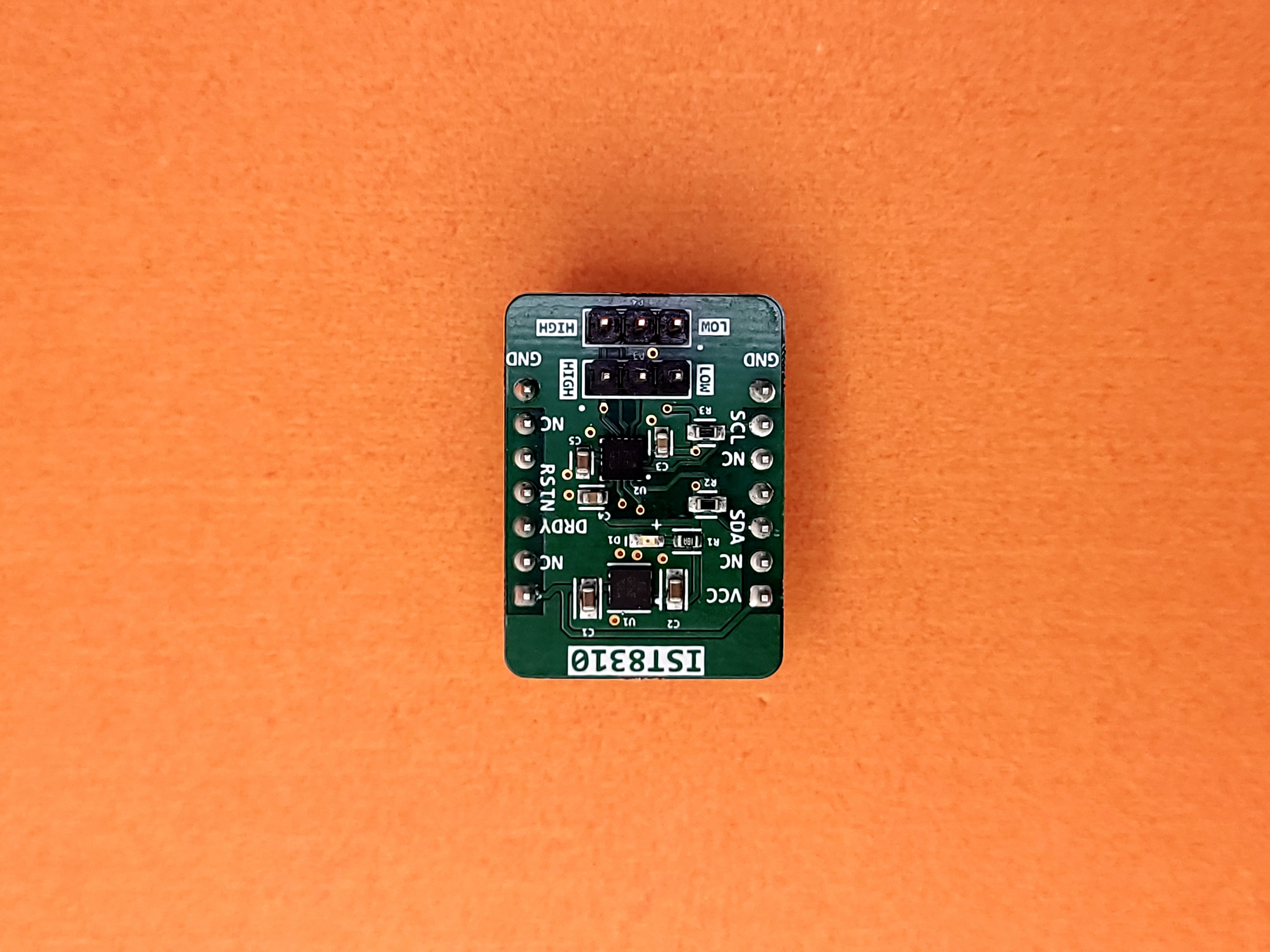
The final board (labelled) looks as shown -
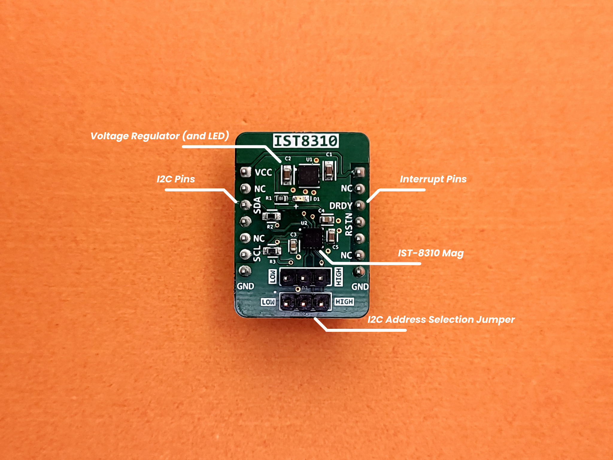
The evaluation board was designed to be simple, breadboard-friendly and re-usable beyond this project. It has the following features kept fairly simple and had the following features -
- Dedicated voltage regulator and power LED - We used the LD39200 voltage regulator from ST, which is an ultra-low drop linear regulator with reverse current protection. The LD39200 has anadjustable voltage output and can supply a generous 2A. Additionally, it has a voltage drop of merely 0.13v at maximum load. Most importantly, the regulator has a wide input range, from 1.25v to 6v. In our case, we wanted 3.3v, and could power the board from an external 5v or 3.3v source without worrying about the sensor burning.
- Separate headers for I2C, Reset & Interrupts - The purpose of the breakout board is to break out the pins of the IC for convenient use. We decided to create separate rows for I2C and Interrupt / DRDY pins on either side of the board, and make it breadboard friendly. This makes it much easier to evaluate the sensor than if the pins were shared and only on one side.
- I2C address selection headers - These allow us to use shunt connectors to conveniently select the I2C headers, without messy wiring or ad-hoc soldering.
- Pull-up resistor on I2C Pins - This removes the need for external pull-up resistors, thus reducing evaluation time.
Apart from its compact form factor and low power consumption, the IST8310 includes ultra-low hysteresis and internal averaging, which help reduce magnetic noise and maintain stable heading estimates even in the presence of nearby high-current components. It also features an interrupt function that activates when the combined 3-axis magnetic field exceeds a threshold (1600 µT), enabling responsive detection of strong external magnetic disturbances.
A potential improvement in the breakout would be the addition of a Qwiic or STEMMA QT connector, which would make the IST8310 easily pluggable into a larger ecosystem of sensor modules, simplifying prototyping and reducing soldering effort.
This evaluation board follows the same form-factor (shape and connectors) as the ICM-45686P & BMP-580. This is an intentional design choice to make the wiring on a breadboard simpler (I2C is a bus and having all the connectors on the same side is convenient to work with). This also makes the development faster.
Since the magnetometer plays a critical role in heading estimation, it's important to mount it securely alongside other sensors to maintain a shared and stable reference frame. The IST8310's standard pin layout allows it to be easily integrated on a fixed sensor board. In contrast, sensors with unconventional layouts or single-side connections often end up dangling on wires, introducing movement and orientation inconsistencies that make magnetic readings unreliable.
Creating a platform-agnostic software driver
After designing the physical breakout board, we needed a robust software foundation to maximize the potential of the IST8310. Our goal was to create a driver that wasn't just functional but adaptable across multiple platforms and projects. This approach aligns with our philosophy of building reusable components that provide long-term value.
Architecture for flexibility and performance
Similar to our ICM-45686P & BMP-580 driver, the IST8310 driver architecture also provides a layered approach with clear separation of concerns -
The key to platform agnosticism lies in our Hardware Abstraction Layer (HAL). We designed an interface structure that defines the essential communication functions -
And functions of the following form -
The init, configuration and data functions implement the logic of executing a transaction with the Barometer, by using the functions pointed to by the interface structure. This allows the consumer of the driver to implement the communication for their platform and communication protocol (I2C).
This structure allows us to inject platform-specific implementations while keeping the core driver logic consistent. Whether we're running on an STM32, ESP32, or any other microcontroller, the driver's behavior remains predictable.
Handling DMA in a cross-platform mannger
For high-speed sampling applications like flight control, Direct Memory Access (DMA) is crucial. Our driver provides both polling-based and DMA-based reading modes.
Specifically when using DMA, the driver provides a function to start the DMA process, and another function which to be called on the completion of the DMA transfer. This allows the DMA read functionality to be performed in a cross-platform manner.
Instrumentation
Beyond simply using the sensor, the driver also includes instrumentation to provide insights into usage and speed-up debugging in case of errors or unexpected behaviour -
- Performance metrics tracking - Our driver maintains statistics on communication speed and failure rate.
- Self-diagnosis - Our driver implemented self-test functionality which works with the built-in self-test functionality of the sensor to give exceptional reliability.
Evaluation process
After finishing the hardware and software development process, the next steps are to thoroughly use the sensor in dynamic environments (such as stationary, vibrating, oscillating etc.) and test various sensor fusion algorithms.
The first part of the evaluation process is to individually test the breakout board and software driver with the STM32F4 MCU breakout board (from the previous part) and STM32H7 MCU breakout board (Coming Soon), similar to unit testing in software development. Once proper functioning has been determined, the next step is to place the sensor in various environments (static, vibrating, oscillating etc.) and characterize its tolerance, power-consumption etc.
After testing the sensor individually, the next step is to combine data from multiple sensors (multiple IMUs as well as other kinds of sensors) to characterize sensor fusion algorithms, which will be covered in a separate blog.
Handling and Assembly Note for IST8310
The IST8310 is rated to handle Electrostatic Discharge (ESD) up to ±4000 V (HBM) and ±350 V (MM), making it relatively robust against static discharge during handling. However, standard ESD precautions should still be followed during assembly. It is also compliant with JESD22-A113 reflow standards, supporting a maximum peak temperature of 260 °C, making it suitable for standard SMT reflow soldering processes.
Conclusion
The IST8310 has emerged as a strong choice for our drone systems, offering excellent magnetic sensing performance in a compact, low-power, and easy to assemble package. We will use it in our flight controller to provide reliable heading measurements and improve the robustness of our sensor fusion algorithms.
Through this blog, we hope to build transparency with our community by sharing our development and engineering process. If you have any thoughts or suggestions, you can share them with us at aerowint.com/contact, or write to our founders directly at milind@aerowint.com or aditya@aerowint.com.